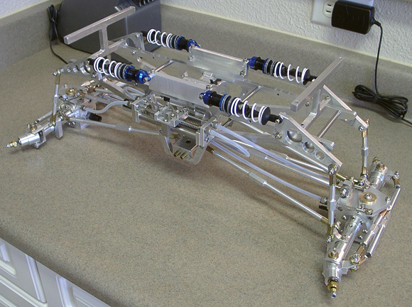
Welcome to my nitro crawler design and build. The information on the following pages details the progression of my RC vehicle from the off-the-shelf machine at its beginning, to the heavily modified and enlarged monstrosity it has become. There are many steps to the process of this design and build, and the original project that inspired this menace was none other than Tamiya's ClodBuster kit. A bit of history about that, and then we'll delve into the custom mess in which I am currently involved. Keep in mind that as many parts as possible have been designed and machined/built by me. The picture below represents the chassis just after the steering work had been completed.
First, some background on the idea. Some sections are dated to reflect the time at which I originally wrote the text.
2-11-2003
When I first ordered the ClodBuster in 2000, I also ordered some aftermarket parts to include in the build, thus starting out with a much more capable truck than was in the kit. I wanted the truck to perform well and be easy to maintain, and there was plenty of motivation for building something superior to what Tamiya had designed. Now, I don't wish to berate what they put on the market, and we all know that this very kit was the beginning of flexible, customizable monster trucks and rock crawlers, and the ClodBuster revolutionized the way in which RC hobbyists looked at their choices and possible vehicles. Tamiya did a great thing by putting on the shelves a truck which utilized both four wheel drive AND four wheel steering.
Now, the main item on the list of modifications to the kit was ESP hobby's Clodzilla IV race chassis. This chassis, at that time, was the leader in race-winning ability and served up several upgrades from the stiff, plastic chassis which Tamiya had designed. The key features of this were a stretched wheelbase (a three inch increase), which offered stability at higher speeds, and a cantilever-actuated suspension system that facilitated an enormous step forward in racing control. I also installed the sway bar kit to keep the body roll to a minimum while at speed.
Not long after the original Clodzilla IV was completed, I realized a distinct lack of solidity. The chassis seemed at once a toy and not at all what I had hoped to control. The rod ends were plastic, and the entire steering and suspension system tended to loosen up under pressure. Unacceptable. This slapped me with the realization that this kit was intended as a toy, and not some superior design for the advanced modeler. Now, it's important to understand that I entered this modeling phase as an adult and as an engineering technician at trade, and someone who had no issues with investing more than $1200 in materials in order to reach a predetermined goal such as a truck that would perform consistent with my expectations.
Following the old truck pictures, there are several shots of the frame rails and other chassis parts which I machined first. I had planned to create a frame that was comparable to the Clodzilla and then extend the wheelbase to 16" and mate it to the JPS aluminum axles via suspension and shock links also made by me. It was essentially a plan to replace everything on that Clodzilla with which I was unhappy. I did not realize at the time, but the project would later spiral into a completely custom job that would serve to both drive me insane and force me into design directions the likes of which I really did not intend to think about.
The next look is of some earlier pictures of the chassis as I was building it. The gearbox, or transmission if you will, is a reduction unit out of an old autopilot from a 1950s era Aerocommander and was to be mated to the Ofna center differential by way of a ring gear through a slot in the chassis plate. The Ofna differential is inside the brass housing below the chassis plate in the pictures below. This was removed and the chassis plate remade in order to redesign the drive train. The frame rails were designed during the fall of 2002 and machined over Christmas vacation. The following pictures were taken on 04/06/2003.
The lower section of the frame holds the lower suspension link mounts and the sway bar mounts (seen below, in brass). This section is the same now, with the sway bars being the only components left incomplete.
A close-up of the center differential and its housing, and the transmission/reduction unit mated to it. Dependent upon the powerplant I chose, the center differential may have remained, albeit in a modified position. Had I opted for 2 electric motors, this center differential would have been unnecessary.
As you can see, the chassis and drive train components differ dramatically from the original kit. I suppose all of the little nitpicks I had for the Clodzilla eventually drove me to this design. Suspension capability and stability at higher speeds as well as size restrictions all contributed to the idea of creating my own design. This first notion started as a rover or other low-speed crawler type of vehicle, and then I changed my mind and felt it needed to exhibit some decent speed and thus had to be adjusted accordingly. Since then, I have returned to the crawler type of vehicle that will utilize lowered gearing to explore. I have no delusions of competition, however. I honestly believe the vehicles with electric power have too much advantage over the nitro platform. In the future a class may emerge, but for now it is merely an experiment.
[While the Clodzilla was electrically powered with a motor on each axle, this newer design was to utilize a single high-torque motor to power the whole model. Retracting drive shafts and a center-mounted differential would be necessary for a single motor. I had gone through a few nitro and gasoline prospects also, and came up with the notion of a twin-cylinder four-stroke engine, but the idea of clean, quiet electric propulsion would be too easy to implement. The truck would then have almost no restrictions as to where it could operate. Recently, I have wrestled with power types and finally settled on a hybrid nitro-electric system for the immense challenge. A 1 cubic-inch offset v-twin will be the engine.]
After the 4 initial frame components were finished, I then machined 16 of my own type of turnbuckles for the new chassis. The aluminum was drilled and threaded left/right for ease of link adjustment and I had cut some threaded rod that connected those links to a set of steel rod ends. They are now fitted to the rod ends and chassis suspension mounts. In all, 8 main links, 4 shock links, 2 drag links and 2 pitman arms were made, all of which are pictured below. The shortest links have not been used. The two drag links in the picture became the pitman arms as the axles became much wider than the stock ClodBuster units. The 8 suspension links have also been lengthened in order to stabilize the wheelbase and ease the complexity of the steering system.
Below is an image of an early stage of the differential housings (assembled with 1/8 scale Ofna gears inside) and a prototype axle tube. The machine work was extensive, especially the alignment of the bearing races from end-to end in order to ensure smooth spinning when under high rpm. The axle tube shown represents the exact size, but the ends would change to ease the machining of each tube as well as that of the steering knuckles. I had decided to utilize stock Tamiya steel axles, half-shafts and stock bearings just in case something snapped.
After looking at the axle tube above, I decided to indeed change the style to ease in manufacturing. The finished tubes are shown below as simplified, and also seen are the spindles and various fixtures that had to be made in order to complete such.
Below is an image of the original JPS axles, after assembly. They included steering knuckles, idler arms, gear cases, motors with heat sinks, and the suspension mounts. Very attractive CNC work, for sure. These were sold in order to finance the rest of the model and to allow me to fabricate my own drivetrain from scratch. This has taken a hell of a lot of time, and some of the design issues have driven me mad at times, but I would rather create as much as possible myself and then leave the purchasing for the electronics and other parts I cannot make. It's funny that in the beginning I had told myself that the axle tubes were too difficult for my skill level. Now I realize that it just took a hell of a lot of patience.
Here we have some more pictures of the work on the axles and associated parts. It took about 45 hours total to complete the work shown here, not including the differentials themselves which were completed earlier in the project. Roughly half that time was spent machining tools and other fixtures and work-holders to complete the machine work on the axle housings, hubs, and suspension mounts.
The images also show the relationship between steering yokes and hubs, and the bearings they held. The steering knuckles now pivot on bronze bushings for more strength. The two longer turnbuckles shown below were originally planned as drag links for the steering, but alas the axles became much too wide for such, and as a result they were discarded and a pair of irregular links are in their place. These can be seen in the latest pictures and will be described further into this text.
The axle tubes seemed too complicated after drawings were made, and I had considered farming out the work to a local shop in order to keep my sanity. In the end, however, I dove in and realized they were not beyond my capability. I'm very happy to have made them myself, and seeing them partially assembled makes the whole endeavor worthwhile.
I suppose the most difficult section was the spindle/axle relationship which must be very smooth or the spinning parts won't last long.
Below, the link attachment points on the chassis can be seen, as well as a closer look at the sway bar pivots which we'll get into more later. The chassis is sitting on a small jack as it would not support itself until the springs were installed.
07/10/2005
A preliminary shot with the axles attached to the 4-link setup, and the 1 body mount in place. This would be the approximate height of the frame over the wheel center, and with tires mounted it sits about 4 inches higher. The Ford body rested at just over 12 inches from the ground all told.
A top view here, and sharp eyes will notice the chassis plate had become absent, along with the original electric motor, center differential and chassis braces. This was because of weight mostly, and also contributing to that change was the fact that each differential would end up receiving its power from a center-mounted motor and gearbox. They will translate rotation through retractable drive shafts and into the input shafts on the differentials. Thus the previous center gearbox is not necessary. Lately, the weight concerns have vanished since there will be no lack of power and due to the fact that I can stabilize the chassis by widening the track if necessary. I believe that a heavier vehicle will enjoy increased traction, unless it becomes too heavy and drive train parts begin to falter. Hopefully, this will not happen.
Above we have a closer end-view of the axle and link mounts, and below is a mock-up of the truck with the F350 body sitting atop.
The body was a lucky find at the nearby toy store, and had been cut from a 1/6-scale RTR kit that proved considerably cheaper than a polycarbonate part. It boasted incredible detail for a toy. Being made of molded plastic, it is entirely possible that the body will not hold up to abuse. It is also heavy (about 3 1/2 pounds by itself) and raises the CG considerably. I may have to operate the truck without it.
07/15/2005
With shock mounts, cantilevers and spacers machined, the chassis began taking the shape of the ESP Clodzilla 4 full race kit. The cantilever design was borrowed and expanded on here, with differing dimensions and shock locations of my own choosing.
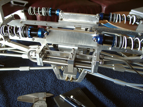
A comparison top view below (sorry about the dim image), and all 8 shocks can be seen in place and ready to go. After a few fittings with the body, it may be necessary to oust the bypass shocks in favor of 4 more coil-overs to support all that weight. As it sits now, the body is empty and will eventually hold batteries, speed control and supporting electronics. The motors will likely be mounted directly to the frame, so that's more sprung weight too.
A closer view of one of the shock pairs in place below. Looking even closer, the cantilever is seen taking considerable stress from only a one-sided spring system. A second coil on the opposite side would even out the pressure and probably last much longer. Worst case, we'll have to change the shock AND the cantilever for something stronger.
The ride height is very adjustable, and I've looked at many setup changes and settled on about 5 inches of fender gap. Any less would likely cause the tire to kiss the fender or bed, and that would not be nice for the paint. In the event that I swap out the Jumbos for a set of 8.5-inch Kongs, I'll put a lift on the body and reconfigure the suspension a bit to compensate. As it is, I may even have to degree the differentials upward to allow for a steeper driveline angle.
Here is a mock-up of the finished product. After assembling the wheel/tire combinations, I decided to set everything up as if it was RTR. The tires were a serious pain in the neck to get on those beadlocks, but once I finished one, the rest went a bit more easily. It can be tough to get the beads inside the grooved wheels.
So far, it looks like the wheelbase is about 5/8-inch longer than the fender spacing on the body. This is preferable to it being shorter, and the only drawback seems to be the body mounts up front not having much clearance for movement. The rods run up inside the dash and to the cowl, and can't be moved further forward. As a result, the body sits a little too much to the rear. I'm sure a couple of adapters should do the trick in keeping center.
The body height is actually lower than I had calculated and it can easily be raised or even lowered as things progress. One of the limiting factors was the interior (i.e. floorboards and seats) so it has been removed and it may be able to be trimmed to then fit inside. This will have to wait until I can purchase the engine, fabricate the cooling system and then locate them around the frame rails.
02/23/2006
After flexing the suspension to its limits, mounting the body and realizing the weight, I decided to alter the setup by ousting the bypass shocks and strengthening the cantilevers. The triangular design is still present, but the cantilevers have been remade both thicker and slightly longer. I have also removed the puny bearings on which the cantilevers pivot and replaced them with bronze bushings for strength. The shock mounts have been cut down after the removal of the bypass units, and the spring rate has been increased dramatically over the previous setting.
Even after that step up in suspension, the more limited travel of the shocks had become a problem. I have ordered a stiffer set of primary and secondary springs to better handle the weight. Fortunately, the new springs are not red and yellow, but a more calm gray and white. This change should yield plenty of travel for my application, about 2 1/2 inches all told.
Below, you can see that the tires are looking rather smallish after the wheelbase extension, and we may be forced into the Swamp Kongs which are 8.5 inches tall as opposed to the Jumbos at 6.25 inches. This will also serve to decrease torque at the wheel slightly, but will increase top speed, allowing for a more civil final drive number.
The tire size seems to be a larger issue than I had first thought. Looking at the truck with a measurement of the body height on the chassis, it is apparent that the tires are small in relation to the same. I have experimented with lowering the body on the frame rails, but anything over about a 3/8-inch drop would interfere with the cantilevered suspension. It is true that the ride height coupled with the weight of electronics would result in an extremely top-heavy vehicle, even considering the decent track it enjoys. The taller tires are no wider however, and would only help to create a more tip-prone design. After the engine and supporting equipment is installed, I believe the CG will be at an all time high. This may require more thought.
I may order the bigger Kongs and check it out, if only to see what difference it makes to the look of the overall picture. I have not strayed too far from the idea of making it as scale as possible, so the larger diameter tires may be a plus toward that end. Another few images of the body before I actually mounted it (finally!) last night. [The only aspect of this which may change is the robotic arm idea that could be attached beneath the bed of the truck, and would only operate with the bed tilted to at least 80 degrees. The worm drive mechanism I was hoping to employ is mostly complete, and tilting the bed electronically is not terribly complex. Likely, it means one more radio channel and a few microswitches. The arm would then be attached by hand and harnessed accordingly. Making the entire assembly removable would be a must if I do indeed go in that direction.]
As it stands now, I'm very close to needing a carload of cash for electronics and radio gear, so it may be the right time to break out the sketch pad and further the robotic design and leave the spending alone for a bit. We'll see what happens over the next few months. I may still shelf the entire crazy business of the arm and focus on the operation as a crawler only.
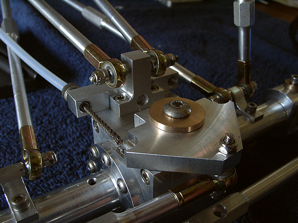
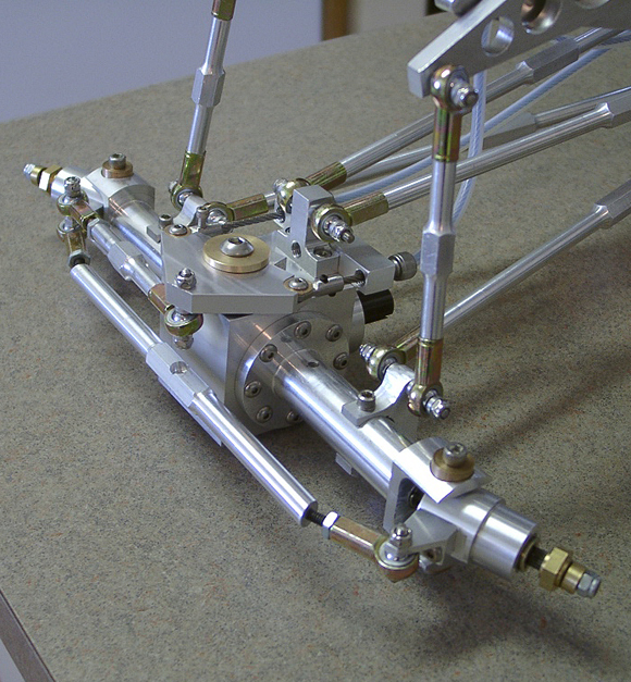
In some of these pictures you can see the original steering mechanics that have been redesigned. The triangular pivots on top of each differential have been remade thicker and with a huge 3/4 inch bronze pivot pin. The cables attach to the inboard end and the pivot is now connected to the steering hub instead of directly to the drag link.
11/03/2006
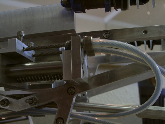
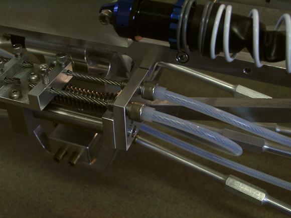
The steering actuation is now moving along at a decent clip. In the last few weeks I have been able to complete an extraordinary amount of design and machining on the supporting components. The tough part has been figuring a way in which to allow the axles to travel up and down with little or no lateral motion on the steering angle. After many hours at the sketch pad (and a few cold beers), the best prototype seems to be a combination of stainless and polyethylene tubing. The rigid tubing will keep the cables taught from the actuator to roughly halfway to each axle, and the polyethylene will allow vertical motion of the lower cable stays during motion. So far, this seems to be working.
11/11/2006
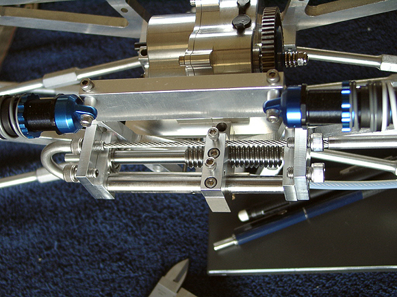
The mechanical aspects of the system are now complete. All four cables are installed and working well, so far. The stainless tubing has been removed in favor of using only nylon tubing for the time being. Until a permanent setup is settled upon, the stainless will remain off the chassis. Nylon is pliable enough to allow some flexibility in the design and will be easier with which to work.
The torque required to turn the lead screw and move the block is much more than I had originally envisioned. As a result, the stepper motor may have to operate at a higher current per phase and a higher voltage to increase the speed. The screw is 10 threads per inch and travels a total of 1 inch to steer the system from lock to lock. The likely interval for this travel will be 1.1 seconds. The voltage can be infinitely varied for whatever overall speed I desire.
The cable ends have not been soldered as I had planned. They are held by offset screws and seem to be reasonably secure. Time will tell if they hold up. The reasoning behind this was to ease the labor required to maintain the system. All of the hardware is stainless steel, which is very temperamental with regard to soldering, and if I have to disassemble anything it needs to be less than a pain in the ass. The fact that the cables loop through the frame in two places also makes it more difficult to disassemble if they are soldered. I still have yet to receive the damned stepper controller and if and when it arrives I will begin testing to evaluate the gearing and current required to operate the insanity... Er... Steering. The system has been complete for almost two months now, and it's still hard to believe that I made it happen.
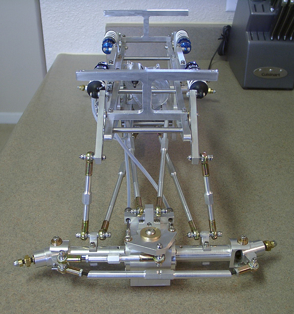
The chassis is standing at about 9 lbs. and just over 23 inches long without the body or wheels. After adding all of the craziness of a cooling system, it may be ridiculously heavy. At this point, I really don't care about the weight. If it gets terribly heavy, supporting components can be redesigned. There are a great many people, both on the Internet and IRL that have been adamant in relaying the fact that this truck will not run, and may, in fact, destroy many of the internal moving parts as a result of my stubbornness in the categories of dimension and weight. They can take a flying leap. I am both patient and determined.
The combination of cadmium plating, bronze, aluminum and stainless steel makes the chassis look quite blingy. This was not my intention, I just have an aversion to putting plastic (or anything too dark) on this truck. Let's just call it a fixation and leave it at that. :-)
Below, the front view of everything assembled as it now sits. That TMaxx transmission is destined to go away. It seems to represent weakness when compared to the scale of the chassis within which it rests. We'll see.